{} .a frame build {
Homemade carbon road frame project.
Can you home fabricate a carbon road frame? I had heard that you could do it with if not minimal craft, at least with minimal means. I asked around but the response from those with experience, riders, engineers, designers etc was that you needed an autoclave – the capacity to compress and heat the composite in a unified moment.
Since then I’ve come to enjoy a very real and refreshing economy of knowledge one that contradicts the doubters assumptions. I don’t have a composite or engineering background, in fact I work in the arts in a world of opinion and subjectivity, so the distinction of trial and error is both necessary and refreshing. If the experience I collect is sound the frame will hold together, if not, it’s my neck! I’ve been fabricating frames for over five years now, although mindful not to over complicate things I continue to develope, explore and refine the process.
See below for build story and posts of developments on other projects. Happy to discuss so leave a comment if you wish to be in touch and please do post any of your ‘homemades’! This blog is a gesture of enthusiasm but without the work that others have previously posted I wouldn’t have known where to begin.
If you choose to use any of the information provided, be mindful of the consequences, I believe it takes a fair amount of craft to undertake a build – I’m simply reporting here that it is indeed possible.
Latest completed frame.

08/06/15
The moulded saddle came out well. It could be formed to a high gloss smooth finish but I find there’s more traction to stop the rider sliding back like this. Also I’ve always like the fabric look of it.


07/06/15
This is a test attempt for a more significant mould I’ll be making in the coming weeks. The first step is to secure your pattern to a release surface and filet the edges to ensure the mould does not gain a mechanical hold. Next is the release agent, in this case a release wax.

The next layer was a thick resin gel coat and once the gel coat had reached a tacky but not full cured state, several resin soaked 100g strand mat fiberglass. I then laminated several more layers of 300g strand mat to finish off.


By all accounts bike manufacturers use automotive clear coats to finish their frames.So far I haven’t paid much attention to my finish as I’m still too nervous following a build about the ride being sound. Usual I get side tracked on another build and can’t stop riding the new frame long enough to strip it back and invest the extra hours buffing and lacquering the finish.
This time however I thought I’d try this MaxMeyer Acrylic product.

12/10/14
New Saddle. Shaped as always from dense Styrofoam but Vacuum bagged to allow me to achieve the concave areas.
 A lower profile than the other saddles I’ve made and at 190g a more competitive weight. I’ve still used the ti rails but this time I bonded the rails directly into the carbon using small sections of the insides of an old Flite saddle. I sprayed the underside black before adding a topcoat of resin.
 The saddle upper was vac bagged over some shaped Styrofoam. I made the shape quite deep to start with so that I could play with the final profile.
2014 . a frame build – Aero tubed frame.
Built bike that I rode today. You may notice the omission of the front derailleur! There wasn’t enough space to attach the ‘band on’ derailleur i was using, I’ll have to shape and rivet on a hanger. Pics to follow.

I also mounted the bottle cages using this handy tool a friend let me borrow. It rivets the bosses into the carbon. In addition I glued the rivets in with structural adhesive just in case the process of drilling and compressing the rivet had propagated any splits in the carbon.

Finally following the addition of hardware and the top coat of Herringbone carbon, tomorrow I will tap the BB shell and build the bike up for riding next week.


I shaped the area between the tyre and the BB alot closer this time. Hopefully the addition carbon will add to stiffness.


Here’s the ‘Sugru’ rubber mold that I formed around the internal cable bosses. I used one on each boss to compress the carbon around the boss. A lot of the larger companies use a similar method at various points around the frame where high compression is desired.


Frame before the top coat of carbon. You can see in these images the different orientations of carbon around the seat post (to strengthen the area to receive the carbon quill seat clamp) and around the joints.


Final layers.

Vacuum bagging the BB area.

Shaped joints –
Work in progress – shaping the head tube. Once these areas were wrapped like the image depicts, I then orientated uni directional (UD) carbon over the joints.

Work in progress – shaping the TT – Seat Tube. Here I was thinking of different shapes but in the end went as simple as possible and removed as much carbon (weight) as I felt comfortable with.
Third generation frame about to be wrapped.

I’m still using a similar fabrication process and geometry but I’ve included an aero seat tube, internal cable routing and an over sized down tube. I’ve bonded the frame before adding the final layers of carbon, which I can now include in the joint process.
Decisions re the frame began with limiting factors, like what seat clamp to go with. I chose the FSA carbon k-wing ISP.

I bonded the frame with 3M Structural Adhesive. I think bought from Transair – http://transair.co.uk/.

The joints. I don’t bother filleting the joint like I did on the first frame, instead I’ll wrap the joints with tow, layering on more (lighter) carbon and then I’ll shape accordingly.


The BB Shell. Bought from Ceeway – you need to contact Peter directly and request the carbon parts you’re looking for. He’s really helpful!

Internal cable routing adapters. Also from Ceeway.

Tube off cuts. They vary in wall thickness. The head tube (top left) has a yellow Kevlar base layer. The seat mono stay (top right) has an internal bulkhead. The two tubes mid left are the ISP off cut next to my Deda fork off cut. Mid right is the top tube and down tube and at bottom the chain stays.

I’ll be using this UD carbon Tow to wrap the joints. Bought from East Coast or Easy Composite.

2013 – . a frame build
The frame rides really nicely but has a totally different geometry from the first frame, the difference in feel was quite shocking.
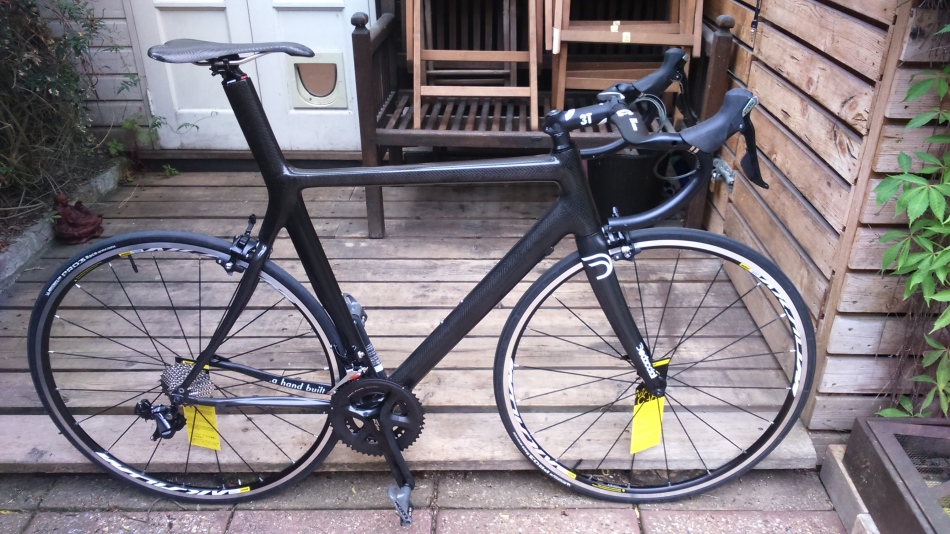
Road and safety testing a new build, ridden for the first time yesterday. Depending on how it feels/performs I may reinforce the BB area before adding a top coat and bottle bosses. It came in at 936 grams before wrapping and with the ISP weighs around 1350 grams now.
USP’s = 1 1/8 – 1 1/2 Head tube – Carbon BB Shell – Sloping seat stays – 215 gram rear end – Carbon dropouts – Triangular sloping top tube and an ISP.
Bike before the final layer.


built a jig for this build.

Pretty happy with the weight considering the ISP. This seems to be a bench mark weight at this size and using this process.

ISP

Carbon BB shell.

1 1/8 – 1 1/2 Head tube.

Carbon dropouts.

The finishing layer of UD carbon. I was at the bespoke bike fair and a friend who distributes Faggin bikes showed me a frame with a hand stitched leather finish. It got me thinking and this finishing coat is useful for hiding any inevitable pin holes in the finish. Looks beautiful in sun light!

2013 – a. frame build
Been away for a while working on these two.

2012 – a. frame build – Homemade road frame project. Hopefully useful for anyone wishing to get on and build bespoke!

The geometry – because this was my first build, I oriented towards what I understood to be a traditional set up. I established the geometry with research from three separate sources: my existing frame (riding position), the Cyfac Postural Manual http://www.cyfacblog.com/downloads/ and as many published frame geometries as I could lay my hands on.

I found that making a drawing gave me a better feel for the logic and dynamics of frame geometry. Given that I had no previous experience, any insight was useful. During the build I shortened the wheelbase and altered the seat tube angle. Clearly not all of the drawing is to scale, that BB shell is way too big.
The rear end: Deda – was bought from Ceeway http://www.framebuilding.com/. I bought the rear end with a steel BB shell and aluminum dropouts. in order to complete the frame I also bought all the bosses, head tube cups and an inexpensive Carbon fork.

The tubes – I started with a sheet of foam board from a craft supplier, roughly cut the tubes to size and refined the shape on long lengths of sand paper.
Any blemishes were filled and smoothed out.

I don’t have the clearest images of the next part of the process. The carbon is cut to wrap the tube the required number of layers in one roll. One side of the carbon is painted with resin. The core is wrapped in carbon and a layer of peel ply is added before the tube is compressed. I used electrical tape, applied with the sticky side out and them perforated with a needle which allows excess resin to drain.

Before wrapping the carbon, I inserted a metal stud for rigidity.

Before the structural layers of uni directional carbon were wrapped, the foam core and stud were removed with Acetone.

The cups were compressed and glued onto the head tube. I figured the plates pressing from each side would help align the cups.

The end of each tube was sanded to seat into its respective join. Where ever there are two different materials (the BB steel to carbon) being joined, the area was insulated with glass fiber. Nasa have release some interesting papers on composite uses, including on the causes of galvanic corrosion.


Part before assembly.

The next step was to build a jig. I was working to a 5mm margin of error, I’d read somewhere that this was common in factory frames. Having said that, with the jig I built, I found it pretty easy to be exact.
The dropouts, BB and forks were fixed using M6 and M16 stud into an MDF box.

The angles were achieve with two pre-cut MDF guides.


I used a section of Unistrut, with some metal parts I had lying around, to create a hold for the seat tube.

The parts were aligned and strapped into position ready for the adhesive.


Once I’d spot glued the frame, it was removed and check for alignment.

Now to flox the joints before commencing with the layups. I created the flox using a mixture of Epoxy and shredded carbon fiber. The flox creates a full weld around the join, much the same as a fillet brazed frame (but without the strength).


Next – shape the joint in order to receive the layups.

All of the shaping was done using 5mm strips of sand paper, in much the same as a fillet weld would be shaped.


Traditionally each joint should, as I understand it, receive a full schedule of layups. This means uni directional carbon being compressed over the joint at something like 0/33/45/90 degrees. http://www.youtube.com/watch?v=l9x2PjozPus – this Cyfac video demonstrates the process. I never really found clear advice regarding the repetition of layers required for each joint. Each area might well receive a different number and will return a different feel and stiffness. I used intuition and common sense, the BB requiring more support against lateral movement etc..
After the carbon (and a layer of Kevlar to protect against chips and cracks on the down tube) has been applied, a peel ply is added, both to help draw out the excess resin and also to enable the compression layer to be easily removed. I used electrical tape to compress the joint, it was punctured with a needle in order to allow the excess resin to drain away.


It is advised that all layers of carbon are compressed in one step, this helps avoid any de-lamination etc. ‘However’, because perfect results are a little difficult to achieve every time, I compromised to allow myself one workable initial multi-directional layer. This layer was shaped and sanded to achieve a smoother bed before adding the final set of layers in one go. I did this in one quick step, trying to complete the full layup before the first layer was fully cured.
It is important to avoid sanding the structural uni-directional carbon, the fibers should remain continuous and unbroken to allow energy to flow and disperse. The multi-directional carbon is more or less decorative and as such it can receive a light sand to smooth the finish.
This image depicts the first and worst joint I made.


At this point I added a few top coats of finishing resin. The resin can be used to fill any minute blemishes and will help protect from UV.  Finished joints.


Next, time to fix the bosses.

Running the front mech cable was a head scratch. I couldn’t think what to use to direct the cable and protect the frame. It occurred to me that the only time I’d seen a cable grommet that size was on the back end of a Bic Biro. So why not. I mounted a steel washer at the exit point and they both work well.


Mounting the gear cables to the down tube was pretty simple. I just molded flox around a pair of aluminum tubes and coated them both in carbon.


Same with the rear mech cable.

…and the brake cables.

Bottle bosses.

In a few spills last year, along with my teeth, I wrecked a couple of Flite Titanium saddles and fancied trying to recycle the ti and builds a carbon version. This was the ‘very light’ out come:


The Ti bars are loose in their fixing and between the (chain ring) bolts and the saddle are a couple of rubber washes, both of which allow the saddle to flex. I made sure I ran a layer of Kevlar through the carbon layers just in case it tried to bite me!! I’ve done several thousand miles on this seat now and it seems both comfy and strong enough.

A few close ups of the finished article, the first of which depicts the Garmin center mount I also made…


Bottle cage 24g

Finished cage.

I forget exactly but I think the total weight of the frame alone was around 1.4kg. If I become g sensitive I know the areas I over spec’ed.
I’m gearing up to build again with more contemporary geometry, shorten the head tube, lower and curve the top and shorten the wheel base. Try to make it more responsive and a little stiffer.
Suppliers:
Carbon:
East Coast Fiberglass suppliers – http://www.ecfibreglasssupplies.co.uk/
Carbonology – http://www.carbonology.com/
Easy Composites – http://www.easycomposites.co.uk/
Frame build:
Ceeway – http://www.framebuilding.com/
The Project Junkie – http://theprojectjunkie.com/
Carbon Wasp –
Brano Meres – http://www.bmeres.com
Research:
Metal corrosion – corrosion.ksc.nasa.gov/ .
Bio-mechanics – Cefac

Did you see this at the week-end? http://www.ft.com/cms/s/2/0fc05f8e-a176-11e2-bae1-00144feabdc0.html
Try using bamboo? xxP
LikeLike
April 15, 2013 at 12:26 pm
I haven’t, many have. Check out Neil’s recent project – http://www.flickr.com/photos/chanceprojects/8589383420/in/photostream and Calfee http://www.calfeedesign.com/products/bamboo/ for the very best.
Cx
LikeLike
April 17, 2013 at 3:15 pm
What was total cost for this Chris?
Jim (Whitechapel)
LikeLike
May 15, 2013 at 11:44 am
Hey Jim,
It’s hard to say entirely. I believe I spent in the region of about £400 (not including the folk). Much of this was start up cost though. C
LikeLike
May 16, 2013 at 7:13 pm
Are you thinking about joining in? I’d be happy to share all my resources. C
LikeLike
May 16, 2013 at 7:19 pm
Roughly how long did you spend on each section of this build – also is it still going strong?
LikeLike
May 19, 2013 at 8:25 pm
I’ve tried to piece together a kind of time frame before, however it’s difficult to say. Working evenings and weekends, I put the bike together in 4-6 weeks. Much of the time I spent was whilst carrying out research. The actually steps, once you know what you’re doing, are surprisingly quick. I’d say sanding and producing an accurate jig were the most difficult time consuming constituents. My advice to anyone wanting to have a go, is to visit a suppliers site (like http://www.ecfibreglasssupplies.co.uk/), buy a meter of carbon, some resin and some peel ply. Buy some foam and some electrical tape and produce something.
And yes I’ve ridden a few thousand miles on it now and absolutely love riding it. I’ve hit several large potholes doing 40+, I’ve even been side swiped by a Nissan Micra and the bike is going strong. Several other riders have commented on its favorable riding characteristics. It’s great.
LikeLike
May 19, 2013 at 10:02 pm
I have worked with carbon in the past and have used similar methods to the ones you have described, it’s now to make the jig and buy the foam.
Good to here it’s still going strong!
LikeLike
May 20, 2013 at 8:04 am
Great, I’d be interested to see any results when you’re done. I’m relatively new to all this myself and only posted my results because I couldn’t find many online resources to glean info from.
LikeLike
May 20, 2013 at 8:21 am
no problem – I’ll keep you updated
LikeLike
May 20, 2013 at 8:51 am
Excelente trabajo y muy prolijo….te dejo mi pequeño aporte http://carbonfiberhandmadeyquediosmeperdone.blogspot.com.ar/
LikeLike
November 3, 2013 at 3:16 am
Nice job dude. I’m thinking of doing this, and i’m wondering about the carbon fiber, how much of each type did you use? also, you said the multidirectional was mostly cosmetic, so did everywhere have uni under? Last question, did you run the uni parallel to the tubes or perpendicular? Thanks!
LikeLike
July 1, 2014 at 9:23 pm
Thanks. Sorry for the late response I was working abroad.
I can’t claim it’s perfect but with every frame I learn more about what’s possible and move on. I’m still riding this frame around happily though without too much… “if only I’d done this”. To answer your Q’s, Yes I now only use uni and the carbon runs the length of the tube with only one or two layers running perpendicular. This was in accordance with how http://www.carbonology.com/ construct their tubes which was my reference at the time. I understand now that a CAD engineered frame would vary orientations to build in compliance and I’m working towards this but in general you want the majority running the length.
I understood from reading about http://calfeedesign.com/ frames that he used a carbon tow to bond the tubes together. So for this frame that’s what I did. Layed the uni sheets in the direction I wanted and then wrapped the joint with tow and shaped.
I have many more photos that I’ve been meaning to add and I’m about to build my third frame. Happy to post new pics if they’d help you?
Keep me posted.
C
LikeLike
July 7, 2014 at 9:06 am
Thanks for the reply! Sorry for the late response too I was out camping. Could i see some pics if you could put them up please? I’m beginning the process of planning out my frame so i can build it when I have a bit more space and cash.
LikeLike
July 13, 2014 at 9:54 pm
Absolutely and happy to help with further inquiries. Bonded another tube set over the weekend so will also post the new build soon. C
LikeLike
July 14, 2014 at 9:39 am
Hi, how much carbon and epoxy was used in total for your frame ?
Regards, Bob
LikeLike
September 3, 2014 at 6:49 pm
Hi Bob,
Thanks for your interest. It’s a good question. The resin quantity is easy – I buy one pack of 1.2kg West System epoxy per build and usually have a bit left over. The slow version if I’m Vacuum bagging and the fast version for compression using tapes etc. The Hardener has a short life span but the resin itself, as I understand it last fairly indefinitely.
I’d say I use roughly 1.5 – 2m of carbon and a small patch of kevlar for the BB and head tube. I use mainly UD (uni directional) carbon but for shaping the BB area the plain weave in the final layers helps.
Get back to me if you require any more info and I’d be interested should you wish to share any build you’re working on.
Regards,
Chris.
LikeLike
September 3, 2014 at 11:02 pm
Chris, few more questions and sorry for my ignorance if they sound simple but I’m really new to this.
What grade of fabric did you use for the tubes and how many wraps of fabric per tube and is ’twill’ fabric the same thing as unidirectional ?
I see you bought the rear end for your frame but would it be ok to make your own ?
Finally did you use normal sandpaper for smoothing off or wet & dry ?
Regards , Bob
LikeLike
September 4, 2014 at 10:55 pm
Hi Bob,
Glad to help.
No uni directional means that all the fibers are orientated in the same direction where as plain and twill are woven. The background to the blog shows a variety with the uni on the left hand side.
I used T300 carbon at 250 – 322g weight. This is about all I have found on the market that is sold in small quantities. I’m working on finding a supplier for better quality carbon but this fabric has been perfectly adequate for the frames that I’ve built. I wrap the core in a plain weave and fill any blemishes or undulations with a epoxy sanding filler.to achieve a strong flat base. Then I wrap approx 2x 3 layers of uni directional and finish with a sanding layer orientated against the length of the tube. I do it in stages on the same day. Use acetone to clean off any any area that you are going to bond to.
For sure you can make the rear end yourself. I’ve avoided it because of the weight penalty I would inevitably pay and because after spending so many hours building the frame, i wanted a finish that competes with a factory built frame. The rear end I use only weighs 219g, I wouldn’t be able to compete with that.
Yes I used all sorts of sand paper to get the finish, but sanding pads and wire wool towards the end of the finishing gives the best results. I tend to coat the frame in a UV epoxy sand it back and repeat the process until the majority of small blemishes are removed. A small sander really works on the joints but be warned, carbon sands really easily!!
Don’t be put off with a bad attempt, you’ll quickly realise how to get better results and how easy and forgiving this material is to work with.
Hope that helps.
C
LikeLike
September 4, 2014 at 11:58 pm
I’m interested on how to make the bottle cage, do you have more infos or video about it ? thanks
LikeLike
September 11, 2014 at 1:59 pm
I don’t, but the process is the same as the tubes and saddle. I’m making another saddle at the moment, I will try to post some further images. Basically I filled an old bottle with fluid (or sand would work), wrapped it in Carbon and then shaped the cage with a dremmel removing the old bottle along the way. Easy in principal but actually quite tricky. I bought some Ti bolts and the cages seem secure enough without any further consideration re attaching them to the frame.
Feel free to ask me further specific questions and thanks for the interest. Keep me posted onany
LikeLike
September 12, 2014 at 11:17 am
I don’t, but the process is the same as the tubes and saddle. I’m making another saddle at the moment, I will try to post some further images. Basically I filled an old bottle with fluid (or sand would work), wrapped it in carbon and then shaped the cage with a dremmel removing the old bottle along the way. Easy in principal but actually quite tricky. I bought some Ti bolts just drilled two holes on the back of the cage and the cages seem secure enough without any further consideration re attaching them to the frame.
Feel free to ask me further specific questions and thanks for the interest. Keep me posted on any results, I’m always interested!
Chris
LikeLike
September 12, 2014 at 11:17 am
Chris,
Love the work and your documentation of it. Really helpful, I have been researching this for a while. Would you mind answering a few questions?
1) I noticed in your early builds some of the tubes (seat tube) look manufactured compared to the different finish on your foam ones? did you just buy these from a manufacturer (like easy composites) and is there any reason you couldn’t use these for all the main triangle tubes?
2) in your later builds it looks like a tapered head tube, is this a deda tube from ceeway?
3) the million dollar question, do you have a rough layup schedule for joints, no one wants to detail this but it seems many use a twill draping layer, UD wrapping, another twill, a final UD wrapping, does that sound reasonable (cloth weight etc. aside)
in the mean time i have been making some saddles and am just finishing up some shoes which are pretty cool (sorry for the crap photos)
Thanks
Sandy
LikeLike
October 20, 2014 at 8:31 am
Hey Sandy,
Judging from your work on the saddle, I can’t wait to see a full frame… really impressive. I know how hard it is to photograph finished work. And thanks for sharing, I’m looking to further the saddle builds so it’s great to have some inspiration.
Yes I bought the tubes from Carbonology http://www.carbonology.com. They do a lot of project work and also supply the motor sport industry. The off the shelf sizes worked with the headsets and seat post I was using so it was really simple. They say that their tubing does get used for bike builds and Parlee seem to use something similar although I know no more than that. It’s my intention to return to use some of their tubing in a TT frame I’ve been commissioned to build. I’ll use their tubes as a core and wrap the airfoil around it. I’d say go for it, but stress your intention when you order, I’ve had a couple of bumpy tubes sent over that don’t look so nice.
Yep, it’s a 1 1/18 – 1 1/2. Either email Peter directly or if you wish I can email you the parts pages he sent to me. He can supply a few different varieties that are not listed on his site.
The joints question is a tough one. How much carbon that’s required is debatable and undoubtedly depend on how the resin will be cured. If you’re cooking the resin and want to reduce weight to the maximum a strict schedule would be required. I stuck a huge amount on the first frame which was entirely unnecessary. The second frame I did use a disciplined schedule of laying down the fibers and it seemed to work fine. To be honest the margin of error seems quite generous and I’ve never had a hint of a problem… then again a failure is a failure.
I’d say relax a little over this one. Lay down UD (I use 300g mostly although it’s tough around the BB) carbon in all orientations and favour a little more in the orientation of maximum stress. The greater the build up the easier it is to compress in an exacting way. I used a UD tow (like the Calfee build depicted on his factory tour http://www.bikerumor.com/2013/06/07/calfee-factory-tour-part-one-how-they-make-bikes/) in the latest build to achieve really tight wrap. I wrapped it in all orientations, sanded to shape, put a few layers of UD cloth down in the key orientations and then finished with a twill cloth. I’d use a tape wrap as opposed to the vacuum bag, I believe you can generate a far great PSI that way. Finally the weight gain when wrapping the joints was less than I expected, so these days I concentrate mostly on stiffness adding cloth where I feel it is necessary.
Hope that helps,
C
LikeLike
October 20, 2014 at 10:10 am
Hi Fantastic build and info, Im wondering how successful are your rear carbon dropouts? Im ‘rebuilding’ a Trek Y Foil from the mid 90’s, it will include integrated headset, PF30 BB and other mods. Im also looking into replacing the rear dropouts for carbon. Ive built frames before but not carbon dropouts. How strong are yours, any issues?
Any info will be much appreciated.
Thanks Craig
LikeLike
January 17, 2015 at 3:57 pm
Hi Craig,
The dropouts on the rear end depicted are built around a slither of ali, I suspects to stop the pinch of the skewer. I wouldn’t give the strength issue a second thought though, I’ve had no issues. Thanks for the intrest and I’d love to see your project! Chris
LikeLike
January 18, 2015 at 5:39 pm
Hi Chris, very nice project I built a tube to tube frame from columbus tubing last year using wet lay up and am half way through starting pre preg one now, I’m in the midst of oven building at the moment. Very reassuring to see that I’m not the only one that overbuilt the frame! likewise having ridden it for a year I’m certain that strength is not an issue. Aiming sub kilo this time so fingers crossed !
Leigh
LikeLike
February 2, 2015 at 8:11 pm
Hi Leigh,
Thanks, be nice to see some images of your builds? Sub Kilo, hope you nail it, I was 250g short but then the frame did have a ISP that must have pushed the weight up. I’m trying to better judge the individual tube layups which I think is where there’s possible weight reduction. Did you manage to source any uni-directional pre preg? My task at the moment is to find a supplier of high modulus carbon and a wider selection of pre pregs, any thoughts?
Thanks for getting in touch,
Chris
LikeLike
February 2, 2015 at 10:49 pm
Hi Chris,
Uni directional is a problem these guys do it http://www.prfcomposites.com/materials/prepreg/ but quite expensive
Tengate, that used to be Amber composites, also do but I’m trying to source some suitable for out of autoclave / vacuum bag only that work at low temperatures as I don’t want the tubes to distort with heat and pressure. I Use DP 490 that has a high Temp rating for the initial joining of the tubes. It would be nice to leave the bearing races in the frame but aluminium has a greater coefficient thermal of expansion than carbon so Im concerned that it might split things at higher temperatures
Ive tried attaching some pictures without success I’m afraid is there another way of getting them to you?
Leigh
LikeLike
February 3, 2015 at 12:06 pm
Fantastic Leigh, thank you, I’ll have a good look at those suppliers. In the past I’ve used a BB shell that comes with a carbon box, it seems to me that they’re quite common on frames these days. The shell has two flat edges which register with the box and in that way solves the issue an over tightened BB spinning the shell. The benefit to this process is of course that the shell is only glued in after the frame is complete. Peter at Ceeway can supply these. I’ve also used Columbus Aluminium fixed cups before but now I build with the 1 1/8 – 1 1/2 prefer to use an all carbon head tube and again mount the cups in afterwards.
To get a full picture can I ask what resins, ambient and/or oven based you’ve tried? As I’ll be trialing the oven soon, if the prepregs aren’t available I’ll undoubtedly stick to infusing my own and will require low/med cure temp resin.
I’m anticipating the reappearance of the many issues we’re touching upon as I build the TT frame!
Shame the picture didn’t come through – you could send them to my work address: chrisaldgate@whitechapel.org.
Regards,
Chris
LikeLike
February 3, 2015 at 12:54 pm
Hi Chris Ill ping the pictures to the alternative address
Leigh
LikeLike
February 3, 2015 at 1:02 pm
Pingback: Transcontinental Race – bar / saddle bags. | Catastrophic Failure